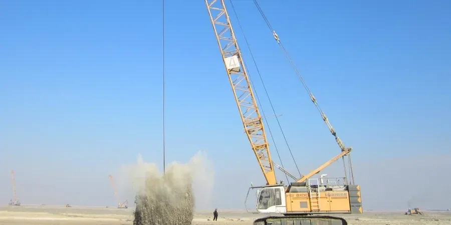
A 20-ton tamper dropped from 25 meters leaves a crater three meters wide in the ground — that is the scale of equipment we mobilise for dynamic compaction design in Chesapeake. The underlying soils here, often soft estuarine clays and loose sands from the Elizabeth River floodplain, demand a carefully calibrated energy input per drop. Before we set the grid spacing, we always run a MASW survey across the site to map stiffness variations at depth, because a uniform drop pattern on heterogeneous ground wastes time and risks differential improvement. The crane positioning, the drop height sequence, and the number of passes all derive from the target bearing capacity we establish during the initial site assessment.
Mapping stiffness with MASW before the first drop prevents wasted energy on heterogeneous ground and keeps the compaction grid truly effective.
Approach and scope
Site-specific factors
In Chesapeake we frequently encounter old dredge-spoil fills that look competent at surface but conceal soft organic lenses at mid-depth. A dynamic compaction design that treats the entire profile as uniform can leave those weak lenses untouched, and the slab above them will settle unevenly within the first year. The solution is to embed CPT soundings at every fifth drop point, correlating cone tip resistance before and after each pass so we can verify that the improvement reaches the target depth. Without that verification loop, the risk of post-construction differential settlement jumps significantly, especially on sites near the Intracoastal Waterway where the fill history is poorly documented.
Relevant standards
ASCE 7-22 (Chapter 20 — Site Classification for Seismic Design), IBC 2021 (Section 1803 — Geotechnical Investigation Requirements), ASTM D1586-18 (Standard Test Method for Standard Penetration Test)
Related technical services
High-energy tamping for deep fills
For sites with more than 20 feet of loose granular fill, we deploy a 20-ton tamper dropped from 25 meters to achieve improvement depths of 8 to 12 meters. The sequence includes an initial high-energy pass followed by two lower-energy passes to densify the upper zone, with CPT verification at 10% of the grid nodes.
Light dynamic compaction for shallow foundations
When the loose layer is less than 10 feet thick and the target is a spread footing bearing at 3 to 4 feet, we use a 10-ton tamper dropped from 12 meters. This approach reduces vibration impact on adjacent structures while still bringing the relative density above 75% in the active zone.
Typical parameters
FAQ
How does the high water table in Chesapeake affect dynamic compaction design?
The shallow water table slows pore pressure dissipation between drops. We install vibrating-wire piezometers at 5-foot intervals and require a minimum dissipation time of 24 hours between passes. If the pore pressure ratio exceeds 0.6, we pause the sequence and install temporary wick drains to accelerate drainage.
What is the typical cost range for dynamic compaction design in Chesapeake?
For a standard 2-acre site with moderate fill depth, the design and verification program runs between US$1.310 and US$3.870. This includes the initial site assessment, field monitoring during tamping, and post-compaction CPT testing. Larger sites or those requiring wick drains will fall at the upper end of that range.
Can dynamic compaction be used near existing structures in Chesapeake?
Yes, but we limit the peak particle velocity to 1.5 in/s at the nearest foundation. We pre-excavate a vibration trench 4 feet wide and 6 feet deep between the drop zone and the structure, and we monitor vibration with three-axis geophones during the first pass. If PPV exceeds the threshold, we switch to a lighter tamper or reduce the drop height.